China
China Deutsch
 English
 ąĀčāčüčüą║ąĖą╣
 Espa├▒ol
 Fran├¦ais
 Polski
 Italiano
 Login
Login
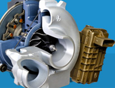
The Rotary Electric Actuator (REA)
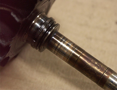
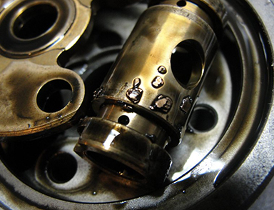
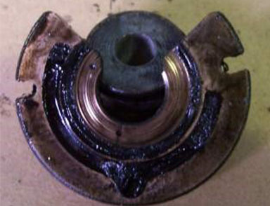
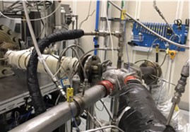
A turbocharger is an air compressor that increases the intake volume by compressing air. To ensure the excellent performance and reliability of the turbocharger, it is necessary to test and analyze it.
1.Two-wheel scanning acquisition and verification
Adopt a portable two-wheel scanning and acquisition device, conduct 3D scanning on the compressor wheel and shaft wheel, and generate visualized data.
.jpg)
.jpg)
The accuracy of blade curvature is controlled within ± 0.40 mm, ensuring that the performance of the blank is consistent with the original, and meets the power and performance matching requirements of the turbocharger and engine.
.jpg)
.jpg)
Scanning comparison NG Scanning comparison OK
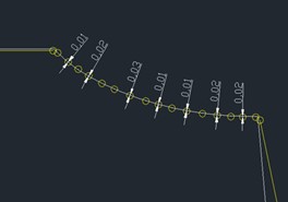
2.Comparison of Two-Wheel Blade Shapes and Lines
Perform 3D scanning and data collection on the compressor wheel and turbine wheel, and align the profile using fiducials (or markers). Compare the results with the original sample, and ensure that the precision control is ≤ 0.1 mm.
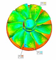
Shaft wheel comparison OK
Compressor wheel comparison OK
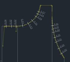
3.Comparison of shell flow channels
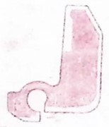
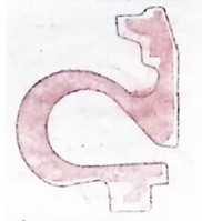
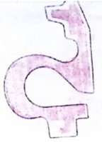
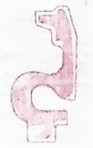
Cut the compressor housing and turbine housing cross-section every 30 degrees in a clockwise direction, resulting in 12 pieces, as illustrated below, with the 0° (360°) direction aligned parallel to the pressure shell outlet (turbine shell inlet) surface.
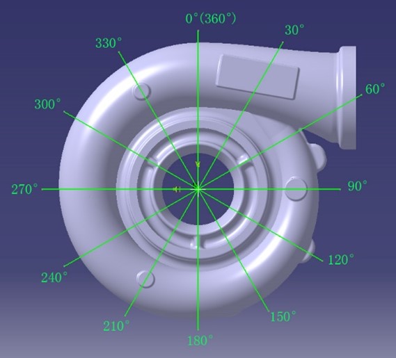
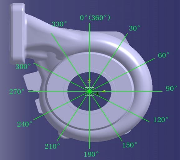
Housings slicing solution
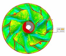
Rubbing the 12 sections of the compressor housing and turbine housing, and comparing them with the OE (Original Equipment), the contour of the section profile of the channel is controlled to be ≤ 0.5 mm, and the wall thickness tolerance of the channel is controlled to be +1 mm/-0.5 mm.
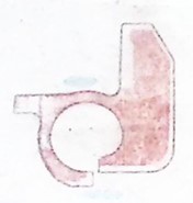
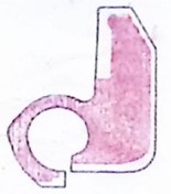
Compressor housing 0 ° section: OK Compressor housing 120 ° section: OK Compressor housing 240 ° section: OK
Turbine housing 0 ° section: OK Turbine housing 120 ° section: OK Turbine housing 240 ° section: OK
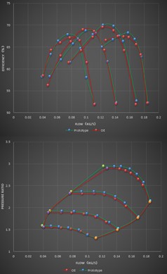
4.Conclusion
After the above testing and analysis, it can meet the performance target control of the turbocharger: at the same speed, the deviation of pressure ratio, efficiency, and flow rate is within ± 3%.
 2020 Jrone All Rights Reserved